![]()
![]()
![]()
![]()
![]()
![]()
![]()
![]()
![]()
![]()
![]()
![]()
![]()
![]()
![]()
![]()
![]()
![]()
Select your Language:
The Laterally Diffused MOSFET (LDMOS) is an asymmetric power MOSFET designed for low on-resistance and high blocking voltage.
Originally designed by Motorolla, then renamed Freescale, then sold to NXP
Observations:
Keep your fans close to (on the fins of) the heatsink. I found its easy to keep the operating temperatures below 40°C while running FT8 or CW or SSB. I had the fans on the back of the enclosure about 1" from the heatsink and could not control the heat properly. Then I moved them right up to the edge of the heatsink, and found that much better (pulling air through the fins of the heatsink).
I find AM mode actually runs cooler than running SSB.Keep the SWR flat to avoid dumping any extra heat back into the heatsink.
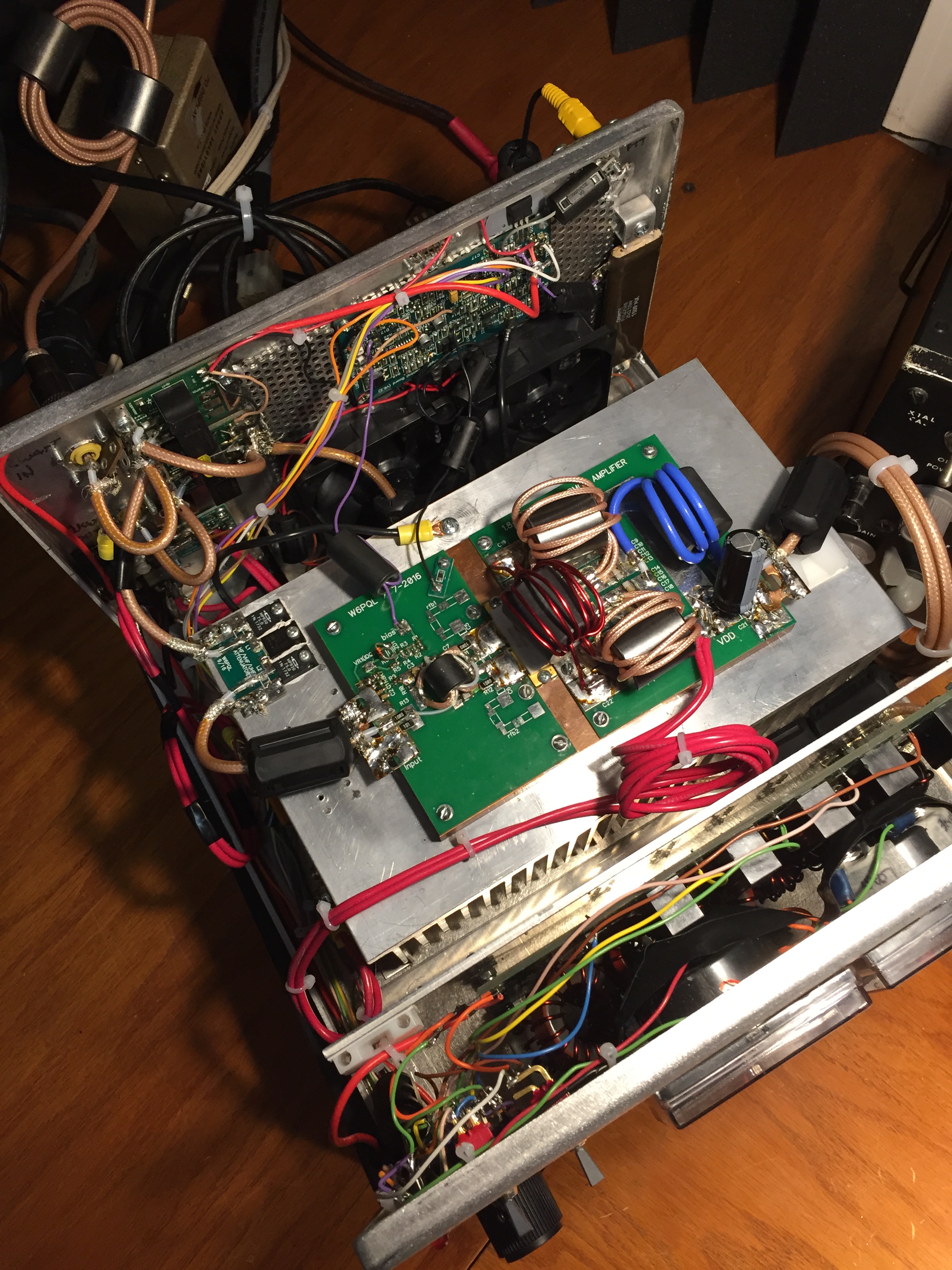
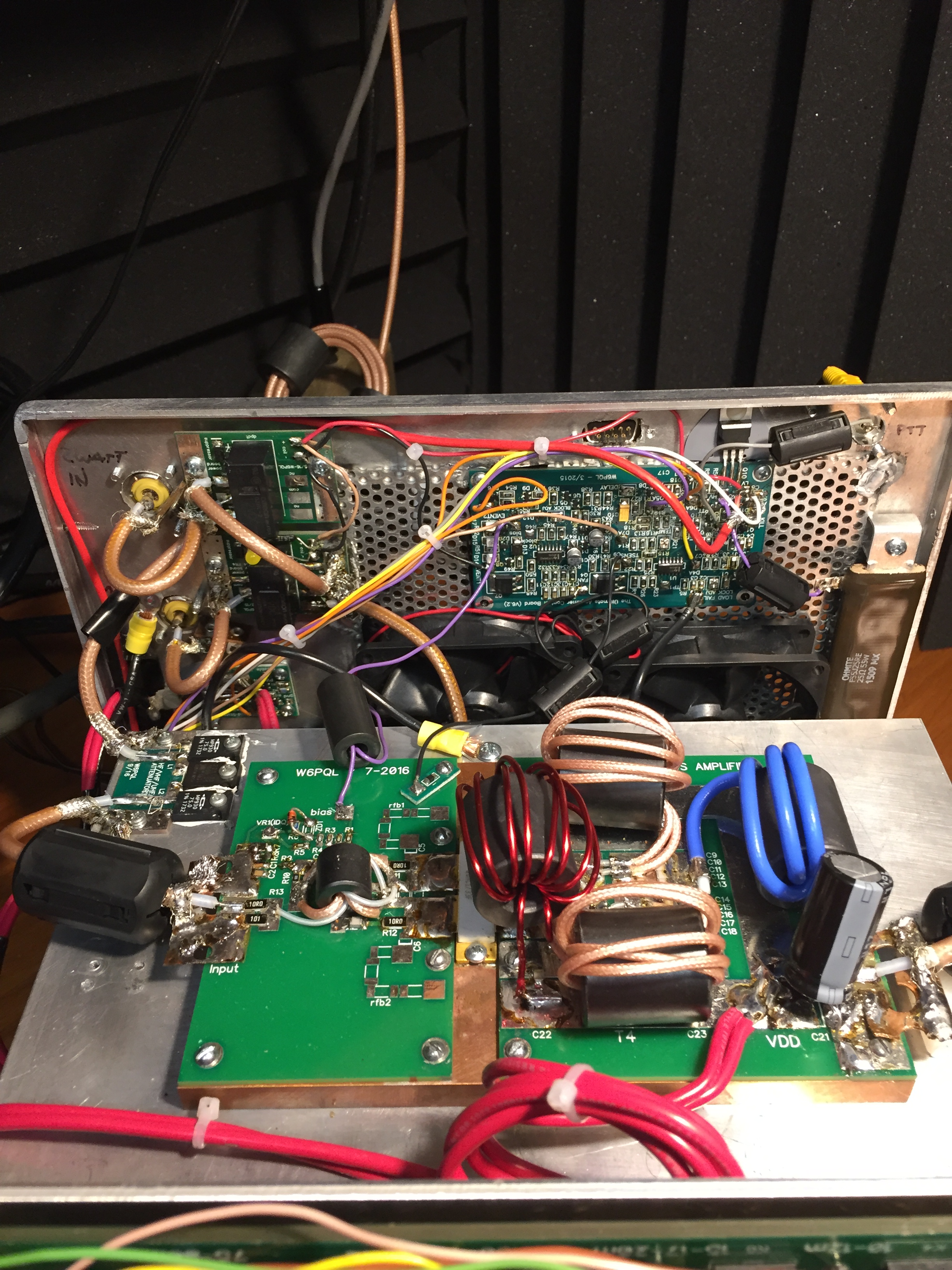
I have also determined that its not necessary to solder the LDMOS directly to the copper plate. I drilled and threaded holes to secure the LDMOS tab, then I created a solid brass clamp that sits over the top of the LDMOS to allow the mounting screw head(s) to sit above the LDMOS. I used hexhead screws with lock washers. Then I polished the mating surfaces and uses a high thermal transfer heatsink grease (i.e. Boron Nitride CW7250). Then polish and apply heatsink grease between the Copper heat spreader and the aluminum heatsink. And I have no issues with heat dissipation now. They even make a Plastic molded version of the MRFX1K80 that has a higher (better) thermal transfer (since the ceramic version is just a ceramic cover with an air cavity, and does not come into contact with the transistor circuitry)
The MRFX1K80 has a slightly higher HF output Impedance of 4.7 ohm, compared to the BLF188XR (3.6 ohms).
The output curve is slightly steeper so its a little harder to control low wattage outputs (below 200 watts)
That means the W6PQL design needs some slight modifications.
First the Bias requires a slightly higher voltage. I changed out the 5.2v zener for a 6.2v and set for .88v on the POT side of R9. I believe I needed to remove R8
You will check swr between the LDMOS and the Filter board and adjust the length of coax between them to get the SWL Down. The Max Id = 43A
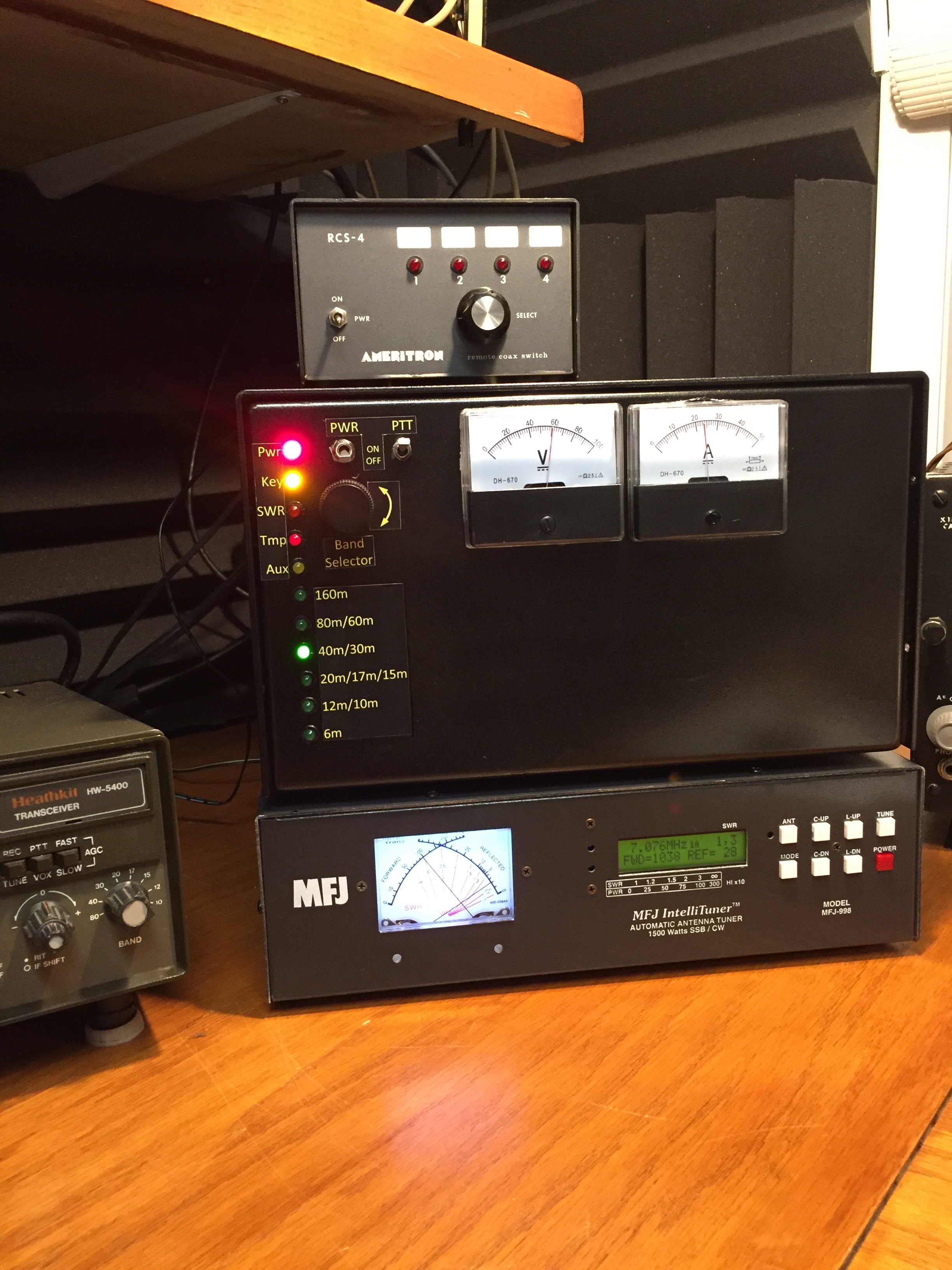
I added a Digital/Analog temp sensor to the front panel, so I can directly monitor temperature on the LDMOS tab.
Also opened up the rear perforated aluminum (near the fans) to increase air-flow
Also added switch (on back) for Digital/AM modes: Keeps Fans on High speed all the time
Legal Limit @ 35amps (Had it up to 1700watts, but my MFJ cant handle it)
Video of LP-500 Tapezoid with my SS AMP:
PowerSDR v2.8.0.83 now controls the Band switching (and Remote Power ON/OFF and remote PTT Enable)
3 Position switch on the Amp allows for OFF/ON/REMOTE Power
3 Position Switch on the Amp allows for OFF/ON/REMOTE PTT Enable (Disable when tunning up)
(See upper left corner of picture below for REMOTE control buttons in PowerSDR)
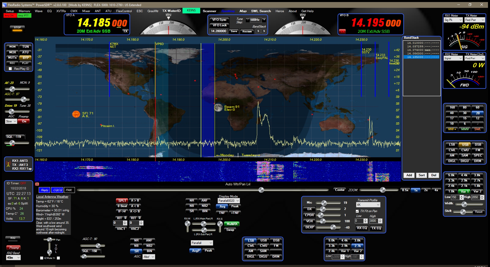
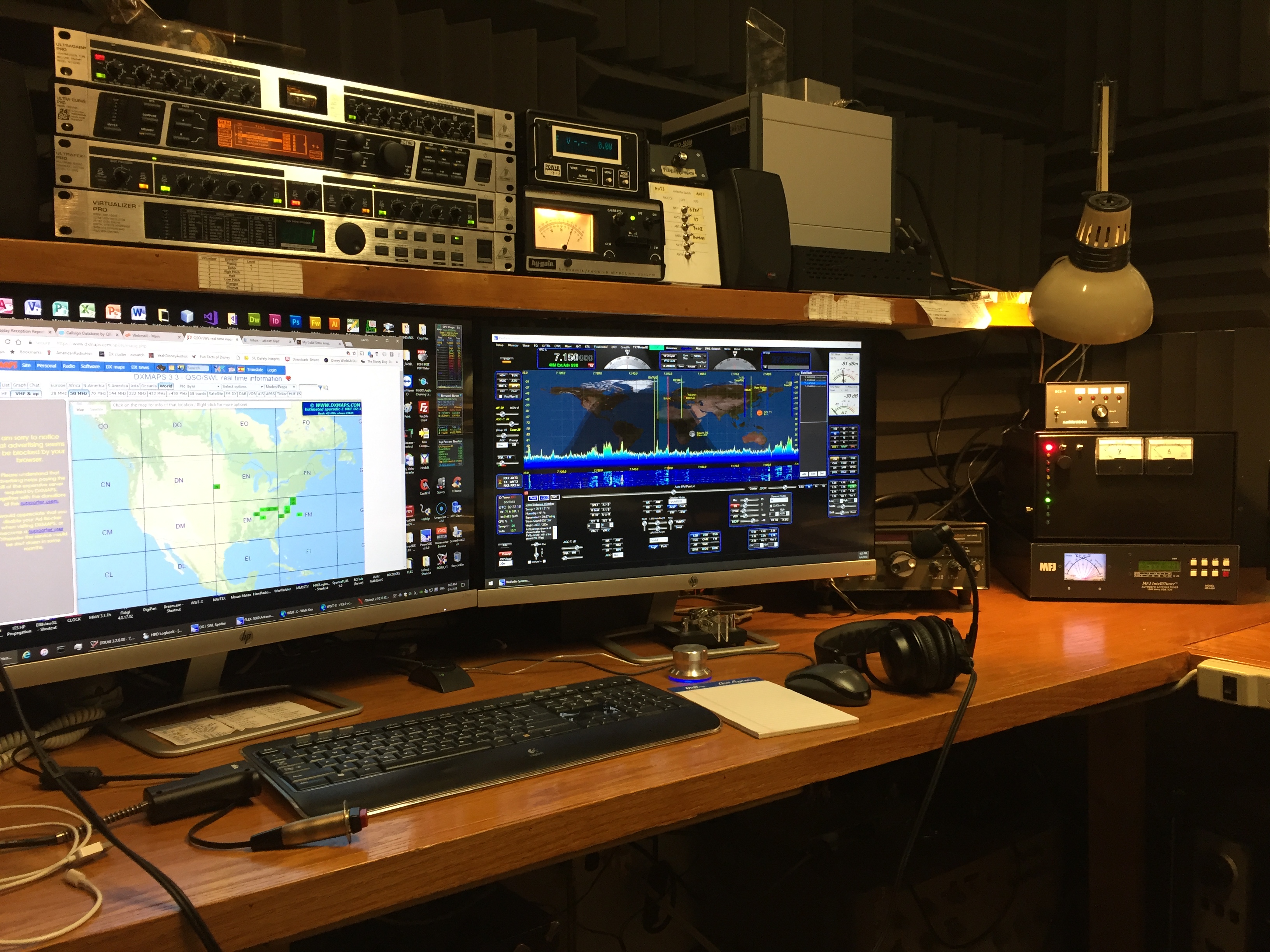
Now have it setup so I can turn the SS AMP ON/OFF from PowerSDR
My new SS AMP in action on FT8 (testing to see how hot it runs). >1kw @ 23A on 40m (with the filter board inline)
CW TUNE up at legal limit (~1500watts)
12" Wide x 12" Deep x 7" Tall
(30cm Wide x 30cm Deep x 18cm Tall)
The RCS-4 antenna switch is actually modified, and is used only to remotely reconfigure the G5RV for 160m using ground radials.
Painted the case metalic Black
THE PARTS:
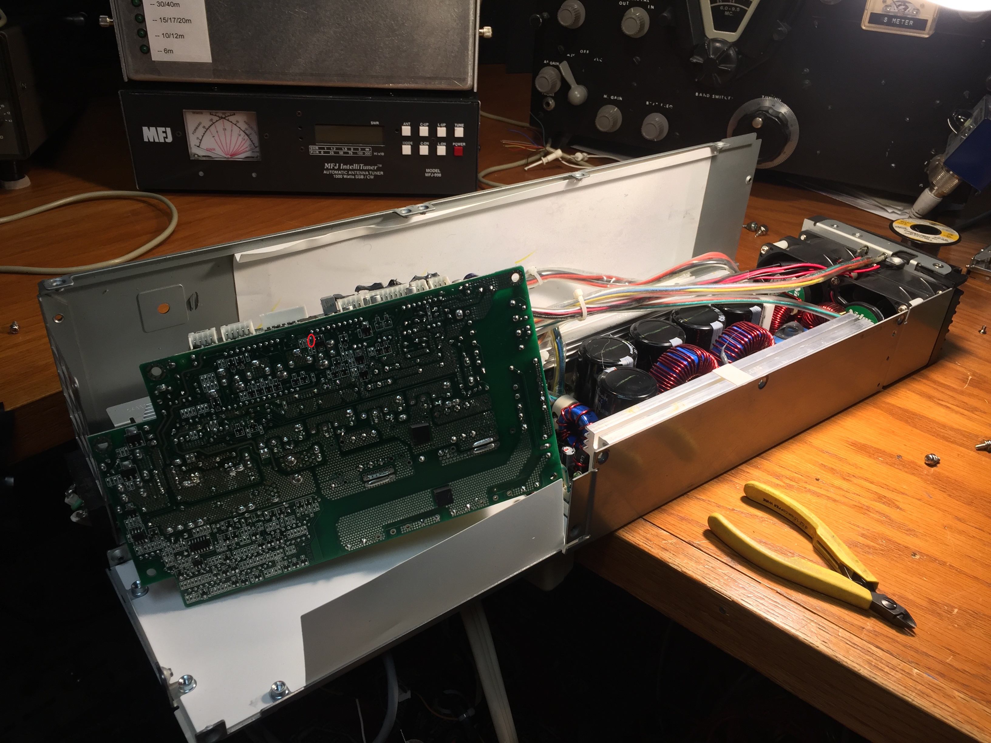
From W6PQL: PA PCB + Copper spreader + Heat sink, and sourced my own parts.
The W6PQL design uses the BLF188XR (1250watts CW @ 50vdc) for the LDMOS transistor pair. You can expect to draw ~30A at 1kw.
(The BLF189XR is an upgraded version (1700watts CW @ 50vdc), but this means the Amps will go well above >30 if your above 1kw)
I went with the MRFX1K80H(1800watt CW @ 65vdc LDMOS). 1.8mhz to 400mhz, handles up to 65:1 vswr. Because of the higher voltage supply, it draws ~35A at 1.5kw
NOTE: I can only get 63vdc out of the ESP120 power supply (with modifications, see down below)
From NXP: MRFX1K80H class AB amplifier will have flat gain curve and low IMD at 2A quiescent current.
NOTE: I had to raise the bias voltage (from the original W6PQL design) to get the MRFX1K80H to draw the 2A Idle current (need around 3.2v at R10).
---------------------------------------------------------------------------------------------------------------------
From W6PQL: 1.5kw Output Filter PCB only (sourced my own parts all 3kv rated)
From W6PQL: "The Ultimate Amplifier Control Board" kit for amp control (for PTT sequencing and protection, and fan control, etc.)
I used (2) 24vdc fans in series and added a 0.5k 5watt resister from "Fan Enable" output to Ground. This keeps the Fans on Very low speed when your not Transmitting (instead of the normal Fan ON only when transmitting or overheat detected).
---------------------------------------------------------------------------------------------------------------------
From W6PQL: Input attenuator kit (13 dB pad) to allow 50watts in for full output (instead of 3 watts for full power which is way too risky)
The downside of the 13 dB Pad is a lot of heat dumped into the heatsink when running digitial or AM modes. I needed to add an additional Fan just for the Pad.
--------------------------------------------------------------------------------------------------------------------
FromW6PQL: Relay boards (for TX/RX switching).
---------------------------------------------------------------------------------------------------------------------
From W6PQL: DC Fet Power Switch (to remove power from PA)
---------------------------------------------------------------------------------------------------------------------
I also purchased the SWR kit from W6PQL, but have not used it yet since I always run the MFJ-998 directly after the Amp anyways.
---------------------------------------------------------------------------------------------------------------------
The Enclosure is my homebrew simplistic design attempt (out of .1" thk heavy gauge aluminum and perforated aluminum panels on the sides and back.)
Video of PowerSDR 2.8.0.83 with my SS AMP:
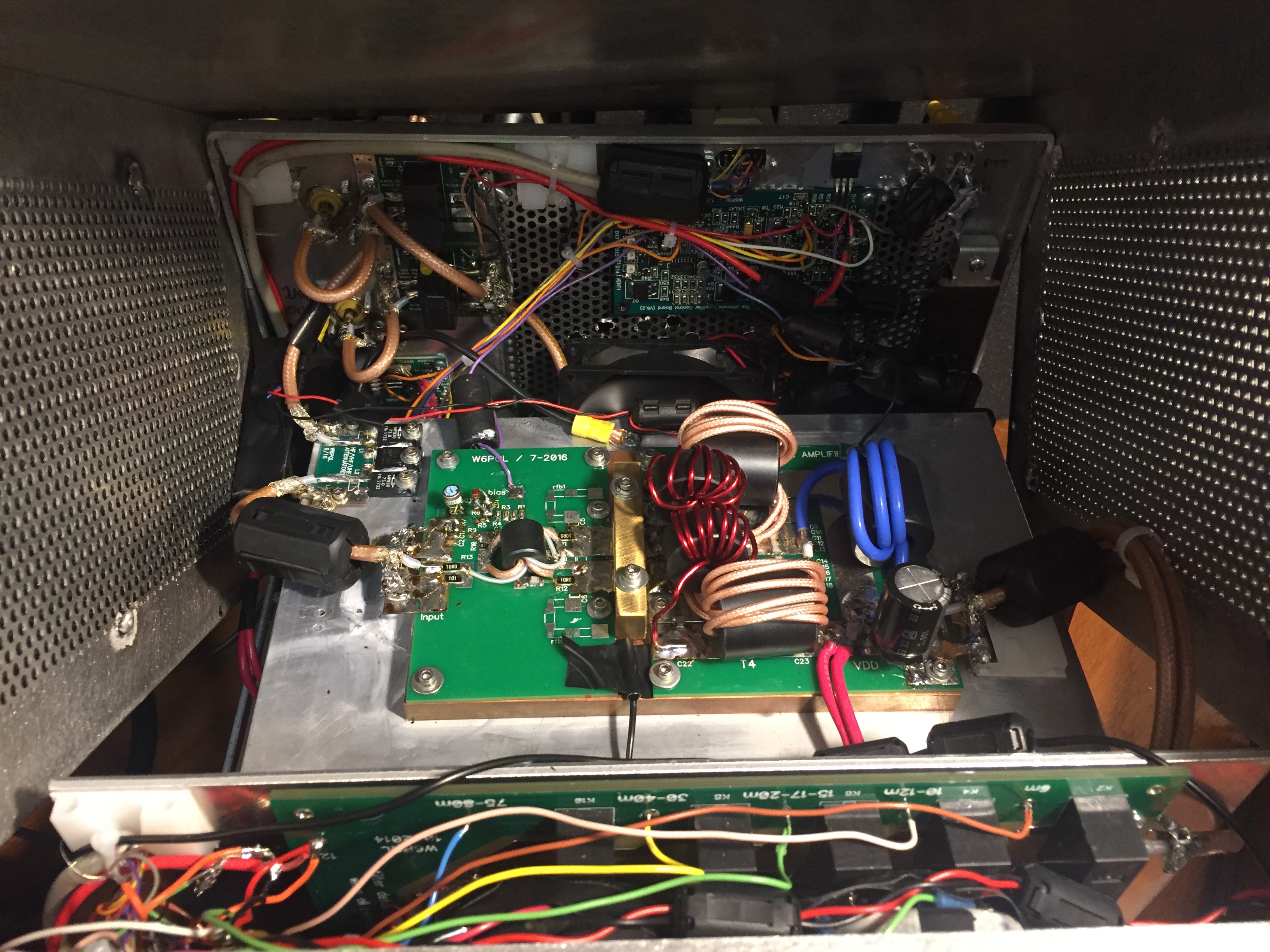
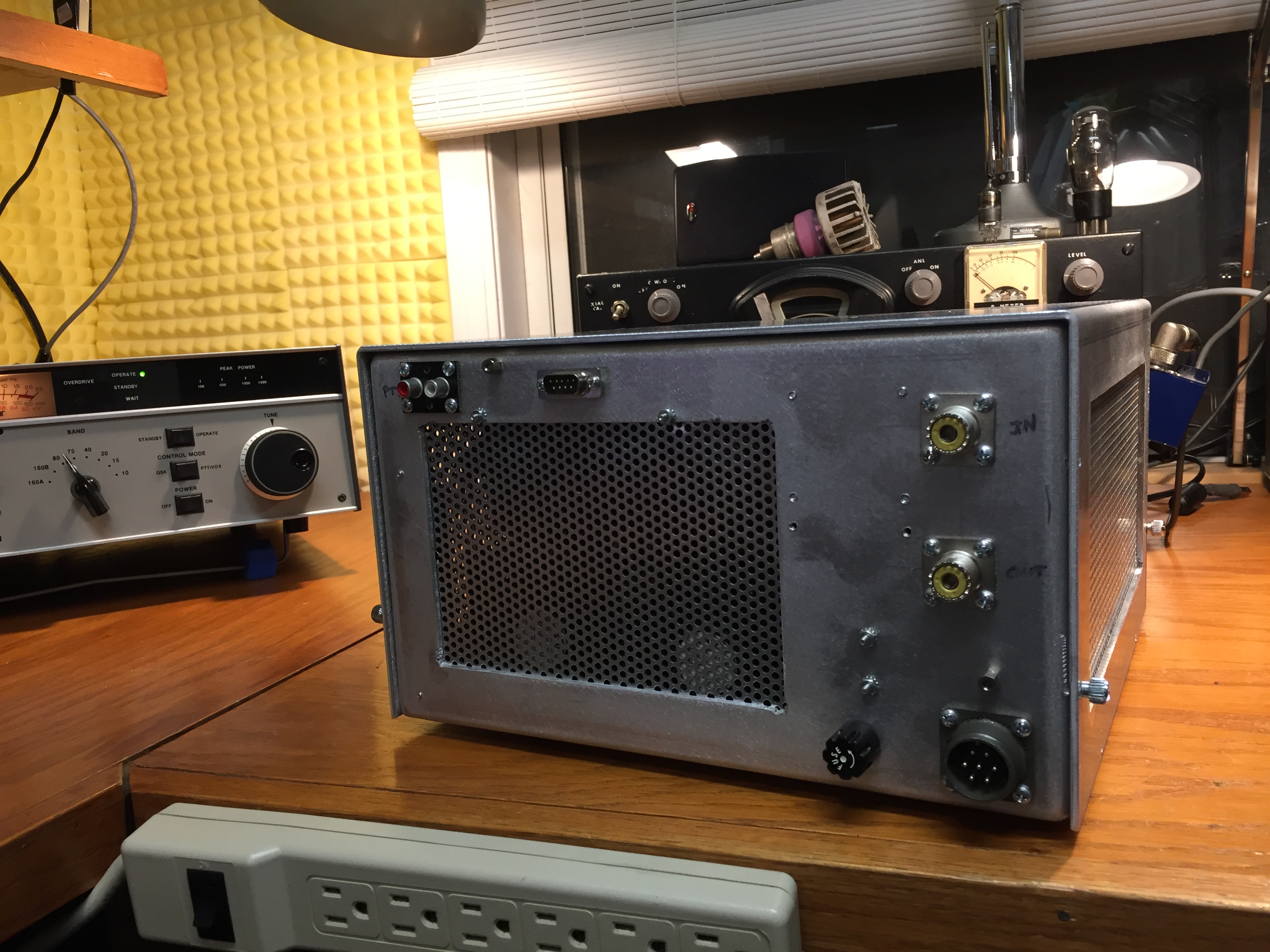
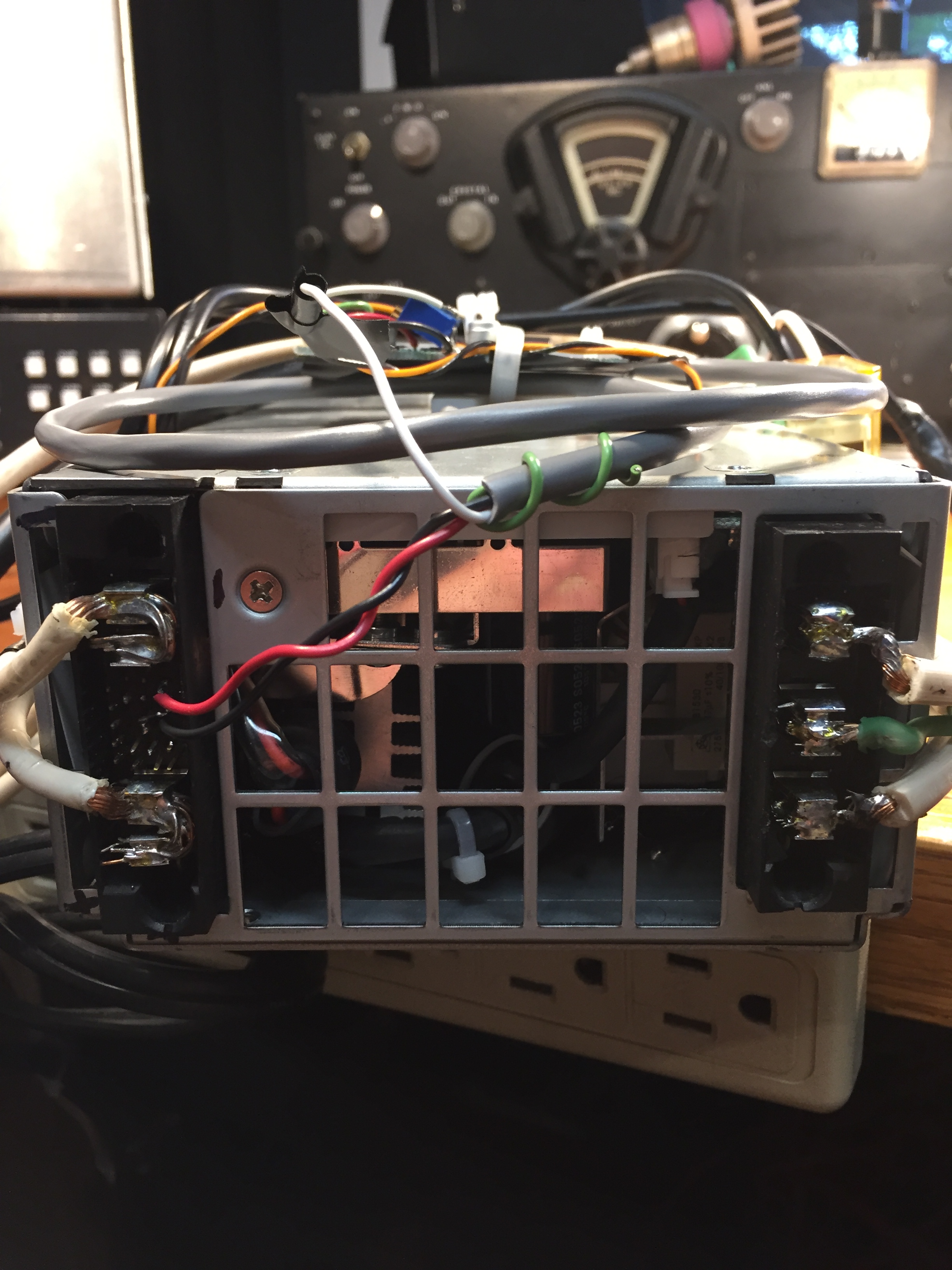
Rear View of my Solid-State Amp .
The DB-9 is used to remotely control the band selection and remotely turn the Supply ON/OFF. PTT is the Red RCA connector.
The military circular connector handles the 64vdc input, and 120vac neutral to turn on the power supply remotely.
Replaced the 3AG fuse (in the photo) with a larger 30A "Midget" Fuse and holder.
Because of RFI issues causing the relays to chatter, I had to place the "Output Filter board" behind a thick .1" Aluminum shield plate.
The "Output filter board" is vertical up against the front of the Amp (between the Shield and the front panel).
You can see the (3) resistor 13db Pad resistors on the left side of the photo.
I hate converting watts to heat, but the Amp is way to touchy if you dont add the Pad (3 watts in would be 1.5kw out).
I just added a 3rd Fan, just next to the Pad resistor to help remove the DUMP heat out the left side of the cabinet.
NOTE: I will need to move the Pad resistors off the Heatsink as they create too much extra heat, and mount them to the bottom of the cabinet. The cabinet is .1" aluminum all around, and so should be enough to dissipate the Pad heat.
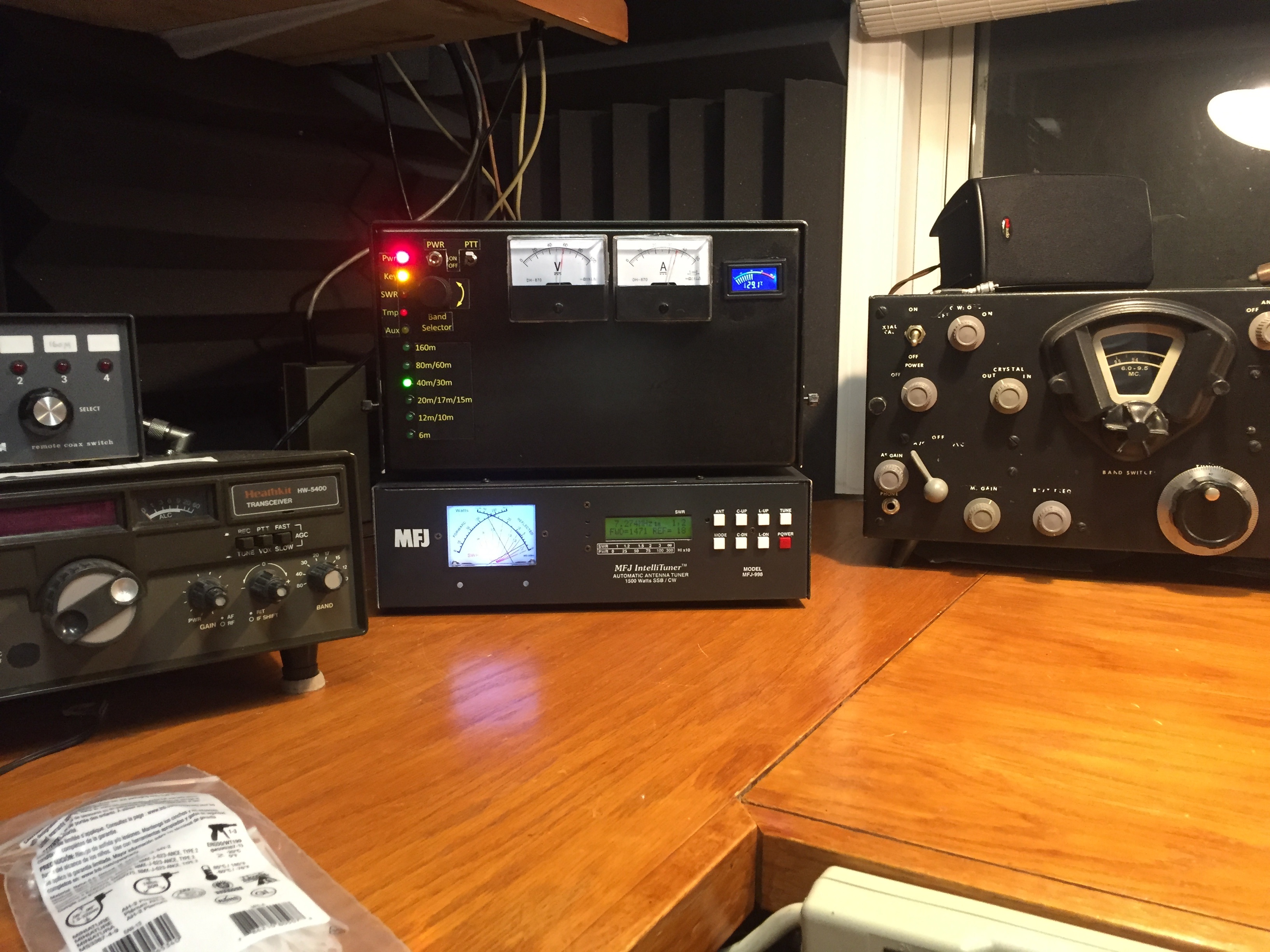
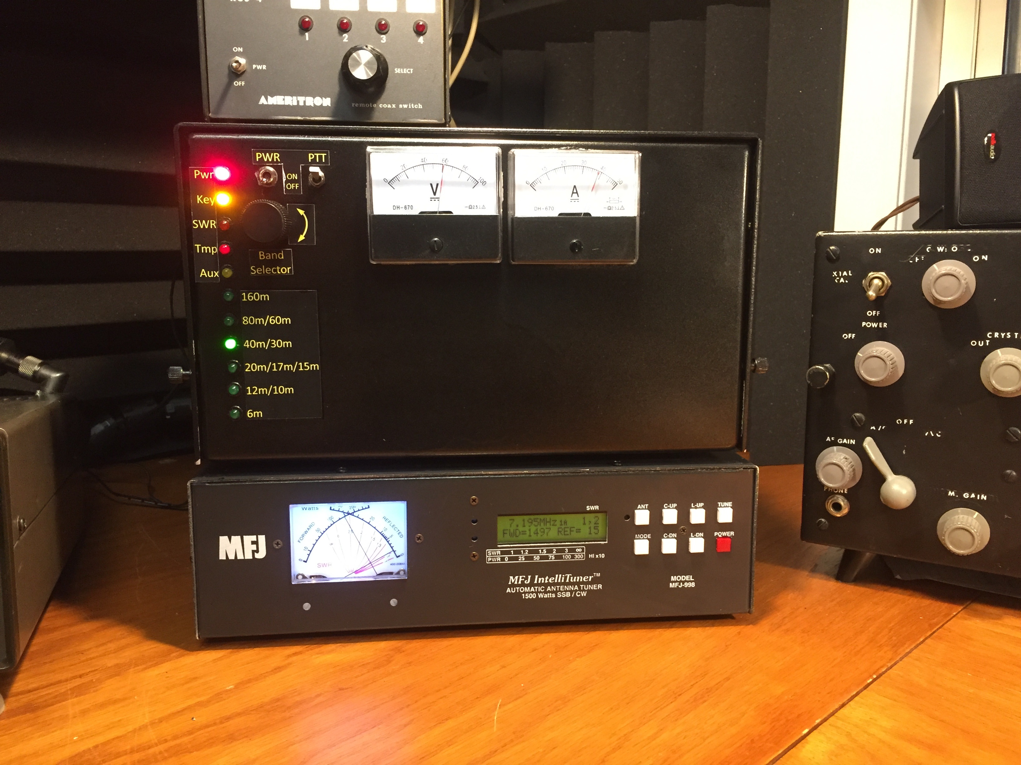
Power ON/OFF/REMOTE (3 position toggle switch) allows for Manual ON/OFF, or Remote ON/OFF
PTT ON/OFF: Allows for Key Enable ON/OFF
Band Selector Allows for Manual or Remote Operation.
-------------------------------------------------------------------------------------------------------------------------------------------------------------
Remote Band Control:
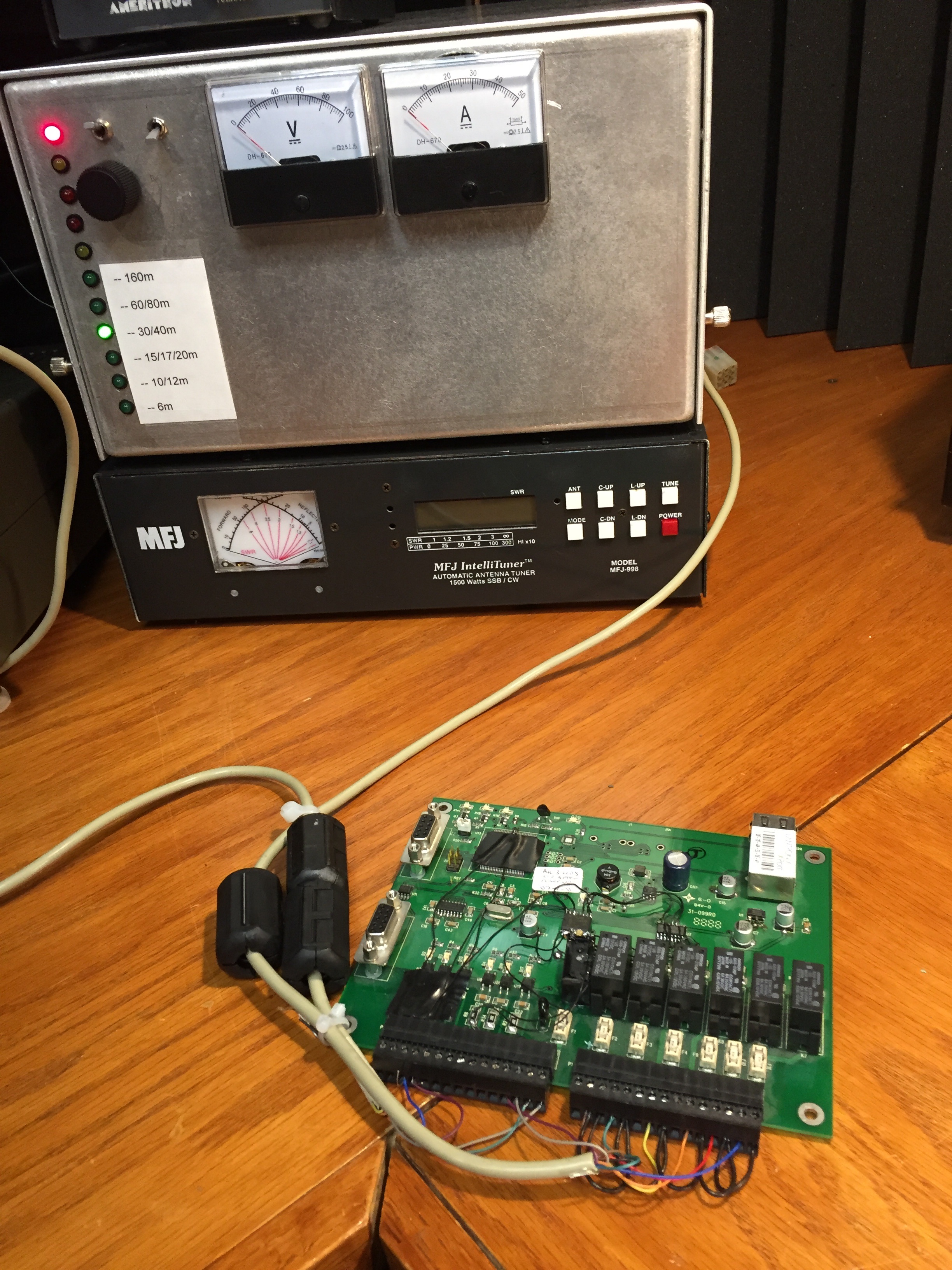
Using a board I designed many years ago that has 6 in, 6 out tied to Ethernet, I modified it by adding a PCS9534 IIC bus Port chip and a 7th relay.
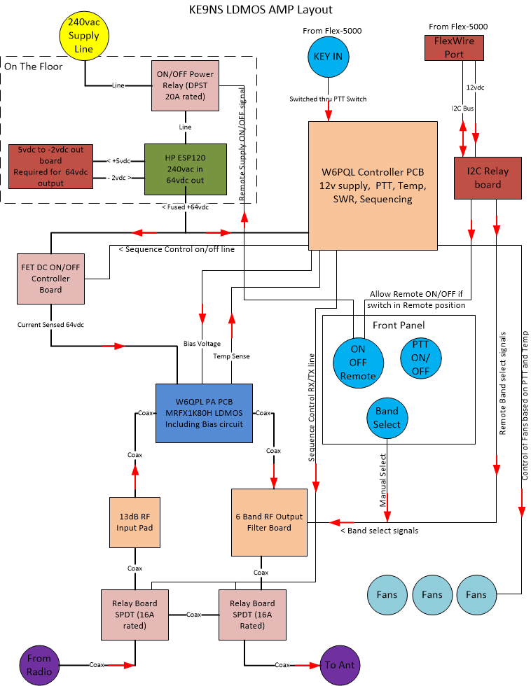
Its a cludge, but its a proof of concept. One cable goes to the FlexWire Port on the Flex-5000 (12v power out, and IIC data), the other cable goes to the back of the SS AMP. This allows for Remote Turn ON/OFF through PowerSDR, and Manual or fully auto band selection through PowerSDR. The MFJ-998 is fully automatic, but lacks a way to read its SWR remotely, BUT I can use my PowerMaster to read the SWR remotely (for now)
Wiring Diagram of my IIC controller interface between the Flex and Amp
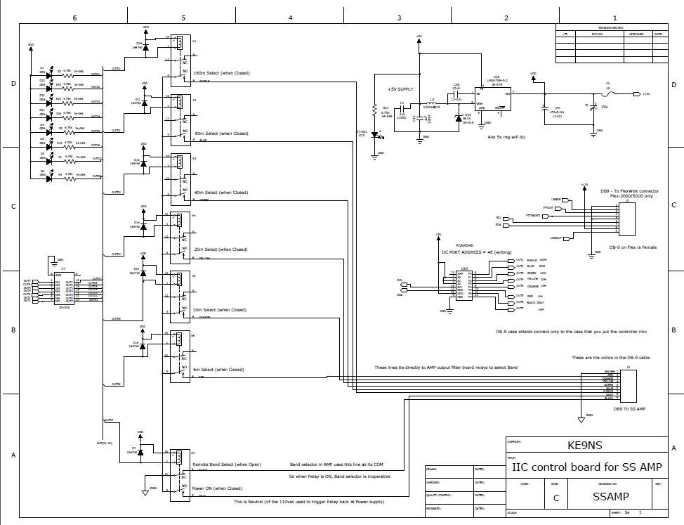
KE9NS Amplifier control using IIC
PowerSDR KE9NS v2.8.0.83 transmits via IIC bus
Activate the feature from:
Setup->General->Options->Use IIC FlexWire for External AMP Control,
and Setup->General->Options->IIC FlexWire AMP ON/OFF checkboxes.
Upon Band Changes the following 12 bytes of data are transmitted via IIC bus:
For the original w6qpl Filter board:
0x4e, 0x01, <DATA>
0x4e, 0x03, 0x00
<DATA>:
bit0 = 160m (L/MW, 120m)
bit1 = 80m / 60m (90m, 61m)
bit2 = 40m / 30m (41m, 31m)
bit3 = 20m / 17m / 15m (25m, 22m, 16m, 14m)
bit4 = 12m / 10m (13m, 11m)
bit5 = 6m
bit6 = AMP ON/OFF
bit7 = VHF/UHF bands (bit0-bit6 = clr, when bit7 set)
---------------------------------------------------------------
For newer Rev6 & Ver2 w6pql filter board:
0x4f, 0x01, <DATA>
0x4f, 0x03, 0x00
<DATA>:
bit0 = 160m (L/MW, 120m)
bit1 = 80m / 60m (90m, 61m)
bit2 = 40m / 30m (41m, 31m)
bit3 = 20m / 17m (25m, 22m, 16m)
bit4 = 15m / 12m / 10m (14m, 13m, 11m)
bit5 = 6m
bit6 = AMP ON/OFF
bit7 = VHF/UHF bands (bit0-bit6 = clr, when bit7 set)
8bit address list for FlexWire output:
0x40 HERO's preselector
0x42 Band selector output for PCA9534 8bit I2c chip (2200m - 20m)
0x44 Band selector output for PCA9534 8bit I2C chip (17m-6m)
0x46 Band selector output for MCP23017 16bit I2c chip (2200m-6m)
0x48 Not used
0x4A LDMOS Amp Filter board selector (w6pql current design)
0x4E LDMOS Amp Filter board selector (w6qpl old design)
0x4C UCB (Universal Control board) PCA9555D Relay selector (part of the Xvtr panel)
See page: http://k3tuf.com/FW.html , for info on FlexWire and UCB
-------------------------------------------------------------------------------------------------------------------------------------------------------------
DC Power Supply:
Power Supply is a (I purchased mine off ebay for $35) HP Server supply ESP120 (an ASTEC power supply with an HP label).
Input: is 240vac, Output: 51vdc @ 57A.
Modifiable to operate up to 64vdc output (requires 2 mods shown down below)
Shown (in the photo below) is my -2.3vdc DC - DC power supply (uses a MAX755 IC) and uses the ESP120 built in 5vdc supply as the power source for my neg voltage supply.
The Relay (right side) allows for remote ON/OFF of the Supply, since the power supply is not designed to be turned OFF.
I only need to switch the Neutral line to the relay (so there is absolutely no current draw) to turn on the power supply.
The relays is a 120vac coil (DPST 20A per contact). I switch both sides of the 240vac line.
The ESP120 has 4 small fans and is very noisy just operating (even sitting under the bench).
So to quiet the fans down:
Add 15ohm @ 1watt resistors on the red +pos fan lead of each of the 4 fans to quiet them down (from N4GA website).
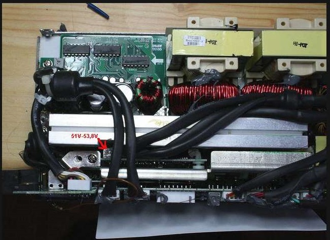
From this photo you can see I was able to adjust the supply to 62.6v, but eventually I increased it to +65vdc. (requires -2.3vdc for 65vdc out)
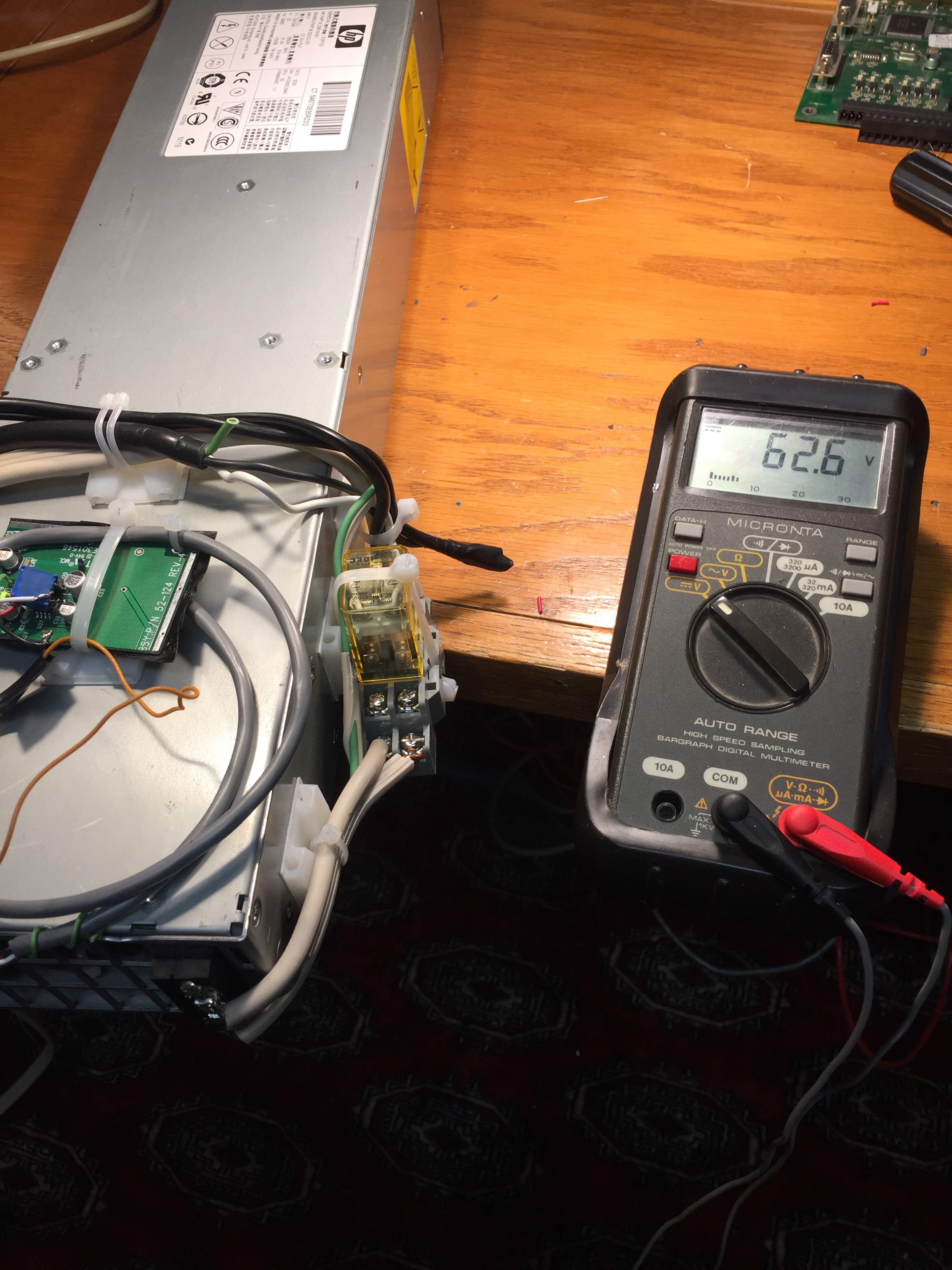
LEFT SIDE: 654vdc output when modifed (normally just 50vdc), RIGHT SIDE: 240vac input
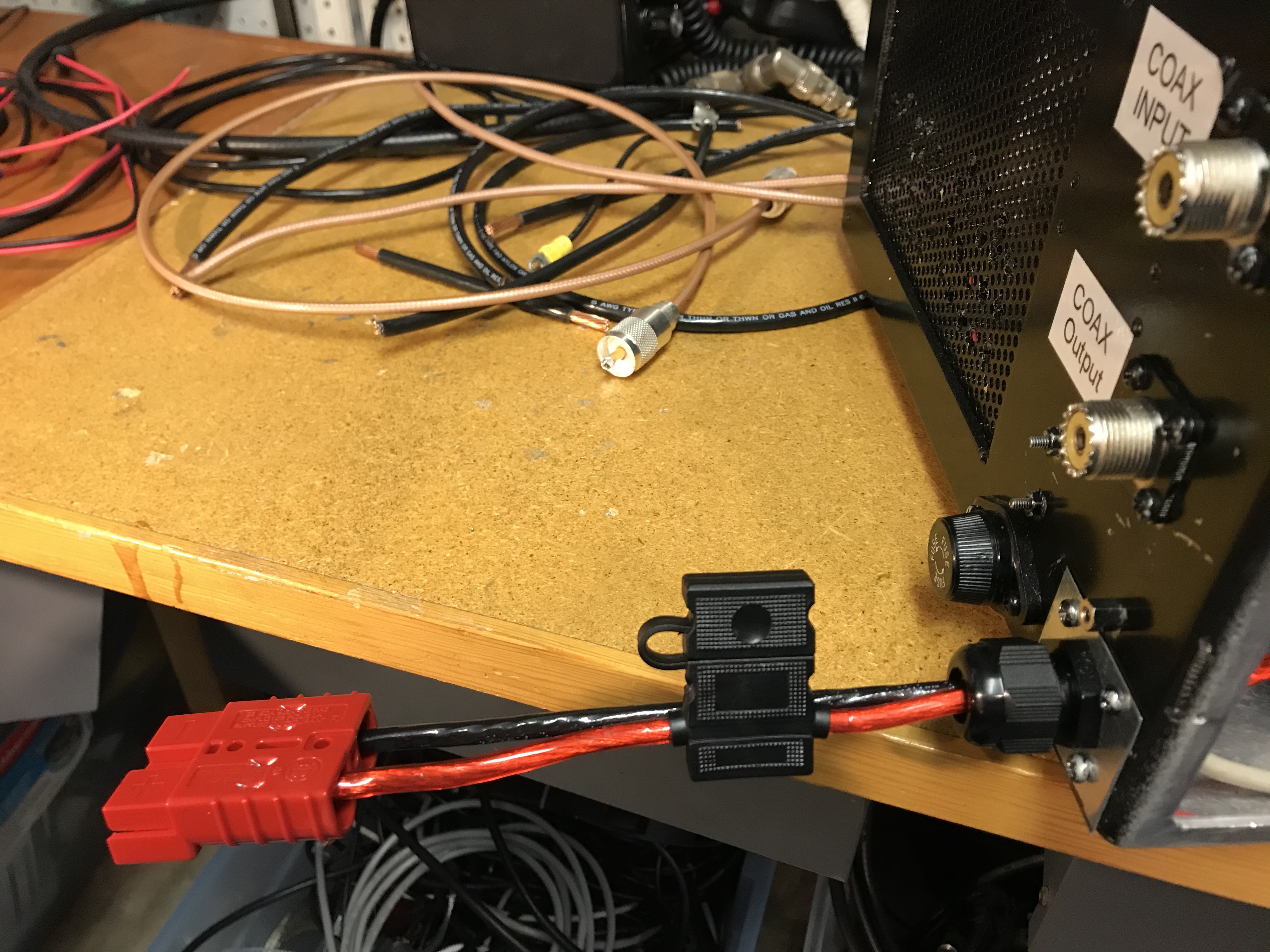
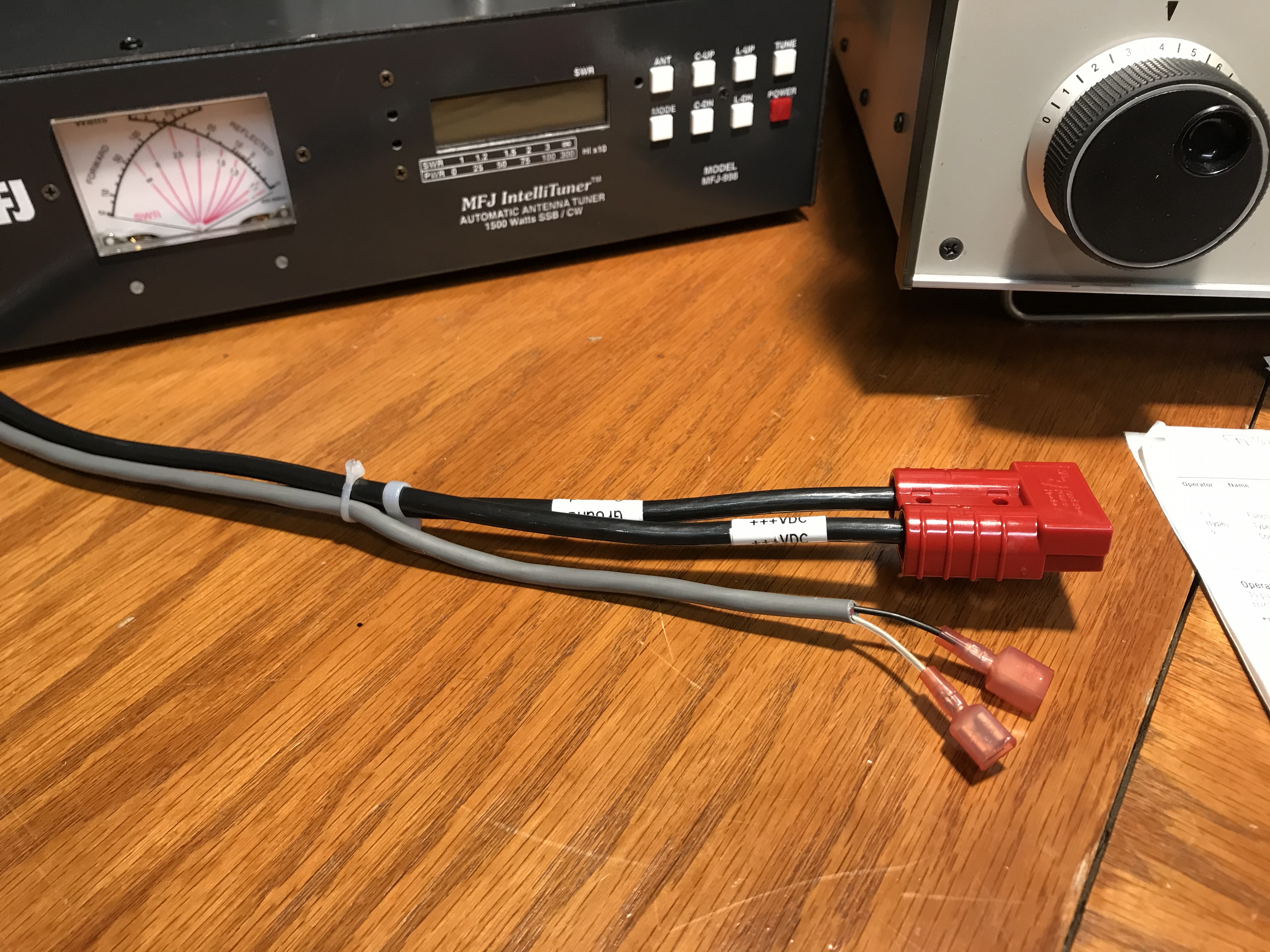
Below: Changed out the original 10' of #10awg cable for 10' of #6awg wire. Removed the orignal AMP circular connector for an 50A Anderson PowerPole inline connector system.
#8 wire from the PowerPole to the Amplifier with an inline blade 40A fuse and cord grip. This helps prevent voltage drop under high loads.
Gray Cable is the signal line to the ON/OFF Relay added to the ESP120 power supply.
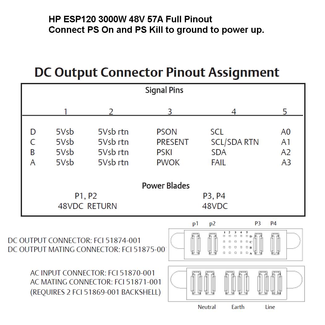
To get the Supply to turn on you must provide 240vac to L, N, G,
and then short the PSON-PRESENT-PSKI pins together (3 pins).
I used a large DPST relay to kill the 220vac remotely requiring only to bring a small neutral line back to the AMP as a ON/OFF switch (and from remote control ON/OFF).
You only need to do the step below if your running a 65vdc LDMOS
Then you need to open up the power supply to remove the potentiometer used to set the output voltage level. The Red Arrow shows the small POT. Remove it and solder a lead to the leg on the side side (closest to the screw in the photo). You need to apply neg vdc to this point to raise the voltage beyond 53vdc. -1vdc = 56vdc. -2 vdc will get you 64vdc output (BUT SEE NEXT PHOTO)
(NOTE: this info was found on a German blog)
Remove the POT from the PCB and I soldered an Orange Wire (black wire is not needed). The Orange wire is where you apply -2 vdc (My neg supply runs off of the 5vsb pins on the back of the ESP120. The 5vsb rtn pin is at case ground)
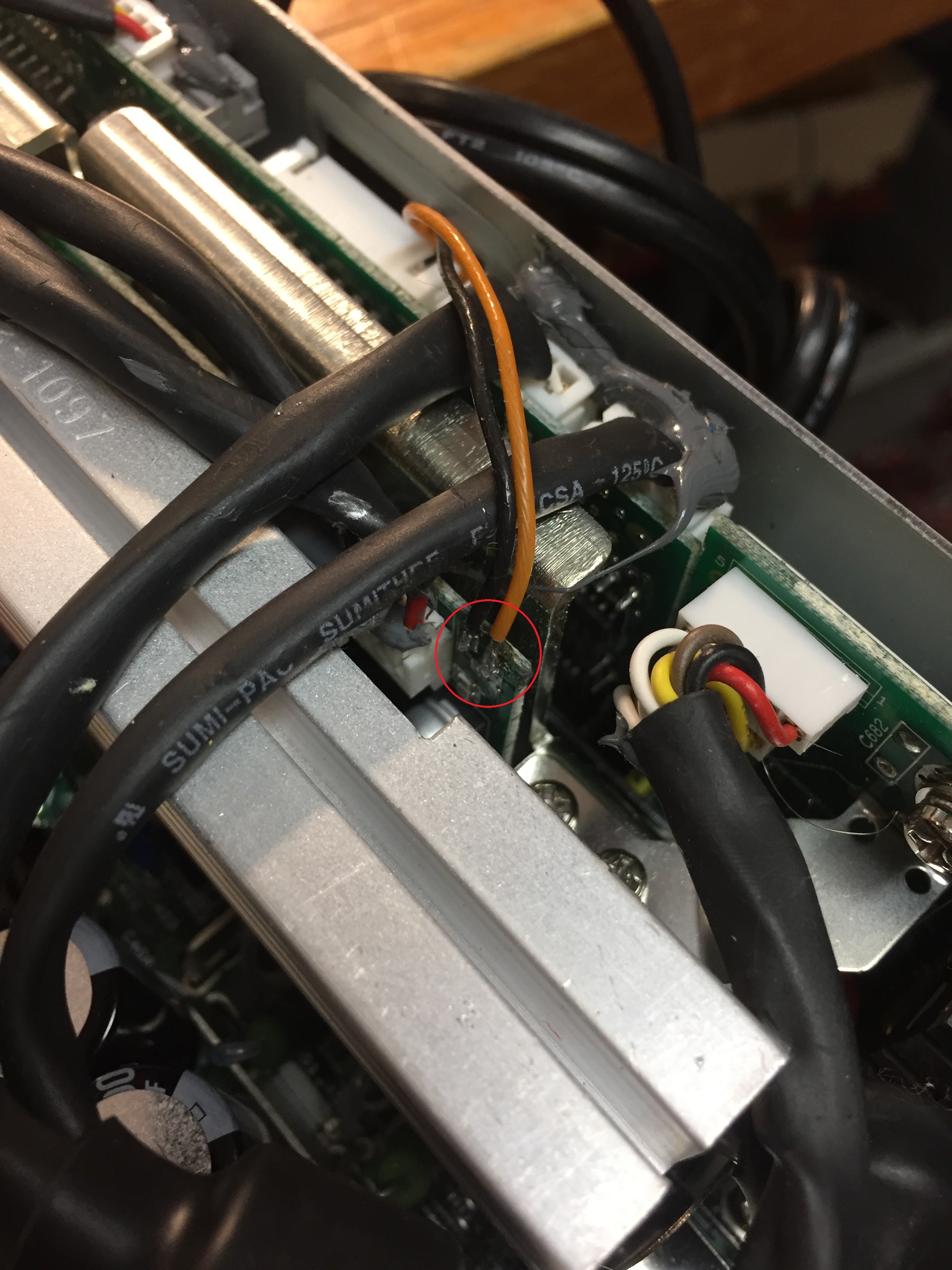
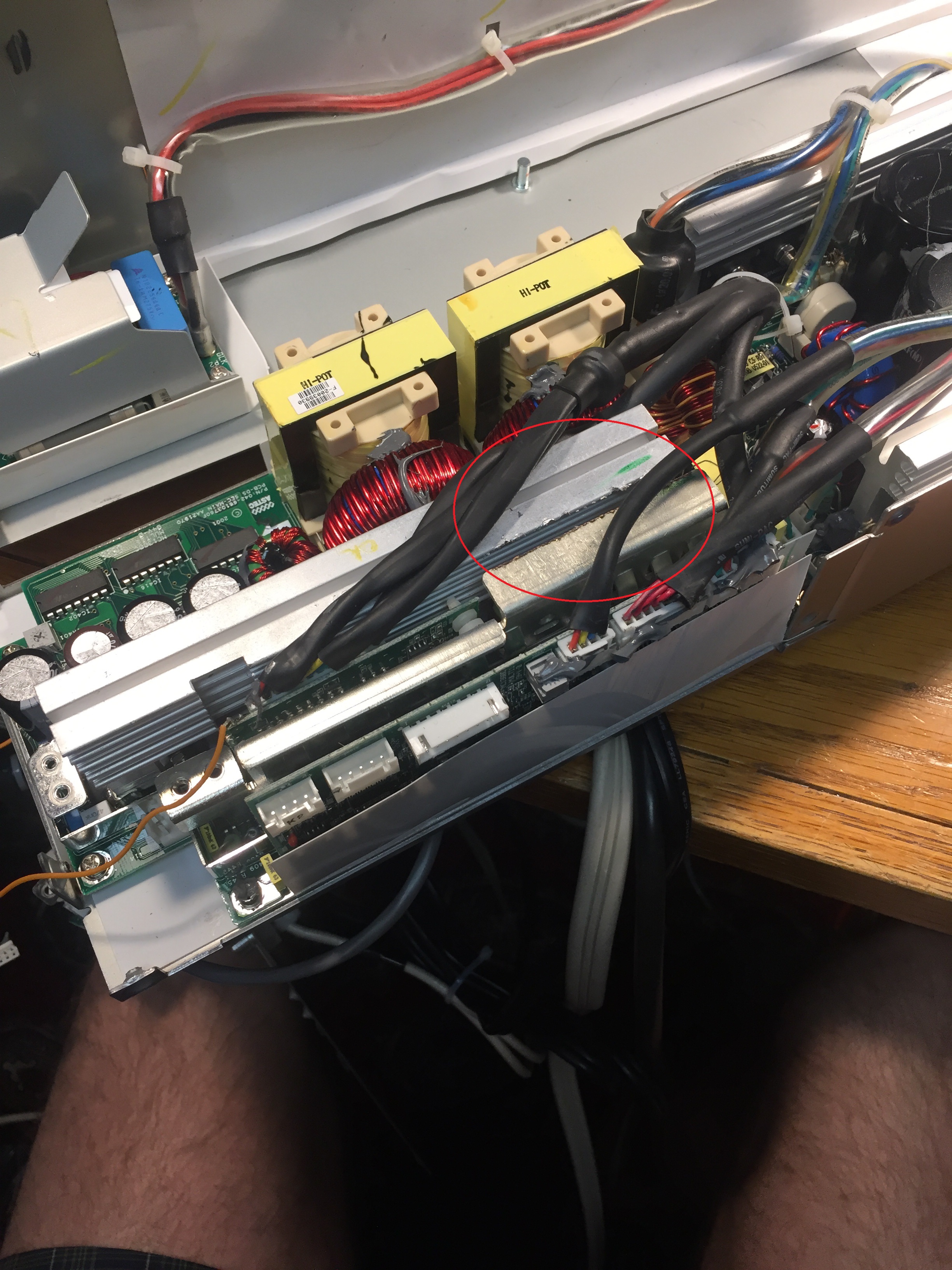
The overvoltage circuit in the supply will cut off power if you go beyond > 56vdc. You can fix this by disassembling the supply and changing out a resistor (as shown in the next 2 photos below circled from a 33k to around ~2.7k.
This board is on the bottom of the supply, which means you need to remove this PCB to get to this resistor (just a few screws).
You can also see the (4) small fans at the front of the supply (very noisy) and the red & black 12vdc supply lines to the fans. Just insert 15 ohm resistors in the Red supply lines to each fan to quiet them down.
Then keep the supply down on the floor way under the bench.
Just make sure when you put the Power Supply back together, these 2 heat sinks do NOT touch each other.