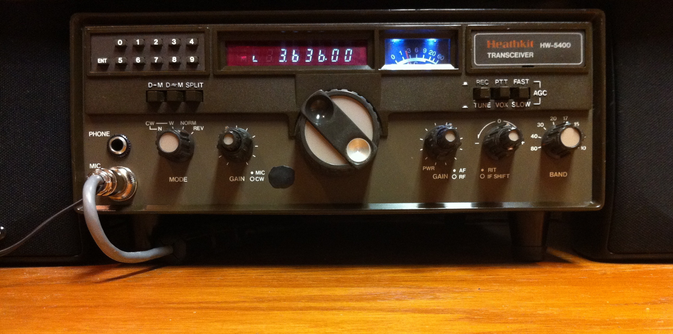
NOTE: Before I modified my HW-5400 with a DDS (Direct Digital Synthesizer) and extra IF filters, I first wrote assembly code (circa 1995) for a Motorola MC68HC11D3 OTP CPU to work on an unmodifed HW-5400.
I made an adapter board to allow the 40pin DIP MC68HC11D3 to plug into the 40 pin DIP socket of the original 6502.
This is the Assembly Code I wrote to replace the original Heathkit 6502 CPU. I did not have access to the Heathkit source code, I just reversed engineered it.
The DDS & Filter board projects replaced many of the boards inside the HW5400 and used
a HC9S12DJ64 (flash programmable) CPU with code written in C (circa 2005)
____________________________________________
IMPROVEMENTS TO THE ORIGINAL RADIO:
1) LO PLL synthesizer (2 boards) replaced by 32bit DDS AD9851 (Direct Digital Synthesizer). Eliminates slew rate issues with 23 million frequency changes / second (.04uSec/freq). Allows frequency resolution below 1hz.
2) Stratum 3 oven controlled crystal osc. improves freq. stability and eliminates most of the DDS generated birdies.
3) LO amp after the DDS increases output level for the 10m band to an exceptable level for the mixer. Original design output was too low causing distortion.
3) Crystal controlled BFO SSB selection replaced by computer controlled 32bit DDS AD9850 IF generator.
4) Audio input selection replaced by self contained SSM2019 full spectrum audio preamp with automatic line level limiter. The preamp directly feeds the balanced modulator and does not allow overdriven audio input.
5) Reconfigured the IF boards 2.4khz crystal 8.830mhz IF filter with a front panel selectable 4.0khz or 2.4khz or 6.0khz 8.830mhz IF filter board. The board uses small signal latching relays controlled by the main CPU to select the TX/RX bandwidth and automatically adjust the IF frequency.
6) Replaced original 6502 CPU with 16bit HC9S12D64 Freescale CPU with Flash memory and EEPROM freq storage. The IF DDS also has its own 9S12D64 CPU.
7) Converted analog RIT control to Digital RIT control with front panel selectable ON/OFF control.
8) Converted analog IF shift control to digital IF shift control with automatic IF shift depending on crystal filter selected.
9) Converted digital main tuning knob from 1000hz or 50hz step frequency selection to 1000hz or 5hz step frequency selection.
10) Performed all MODS from issues of QST (see link below for listing)Below is a short youtube iphone video I took showing the HW-5400 with the DDS boards working.
Below is a short youtube iphone video I took showing the inside of the HW-5400 with the DDS boards.
Below is a short youtube iphone video I took showing the HW-5400 with the DDS boards 2.4khz, 4khz, 6khz crystal filter.
CLICK HERE TO FOR list of HW-5400 QST MODS (.PDF)
Right click (below) to download each PDF
..
..
.jpg)
..
Before I modified my HW-5400 with a DDS (see the DDS Project page), I first wrote asm code for a Motorola MC68HC11D3 CPU to work on an unmodifed HW-5400. I made an adapter board to allow the MC68HC11D3 to plug into the 6502 socket. This is the Code I wrote to replace the original 6502 CPU.
Heathkit Matching Accessories
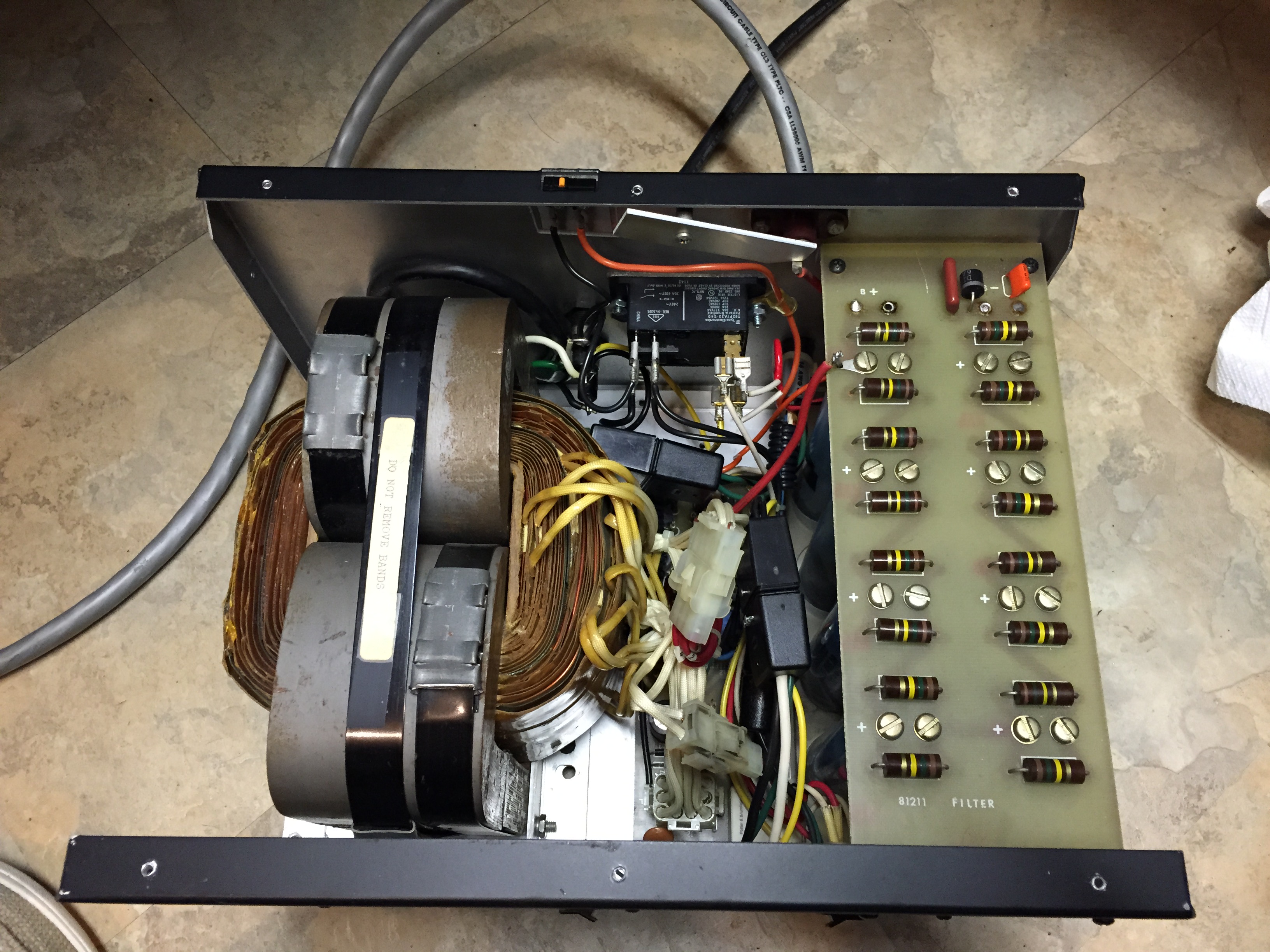
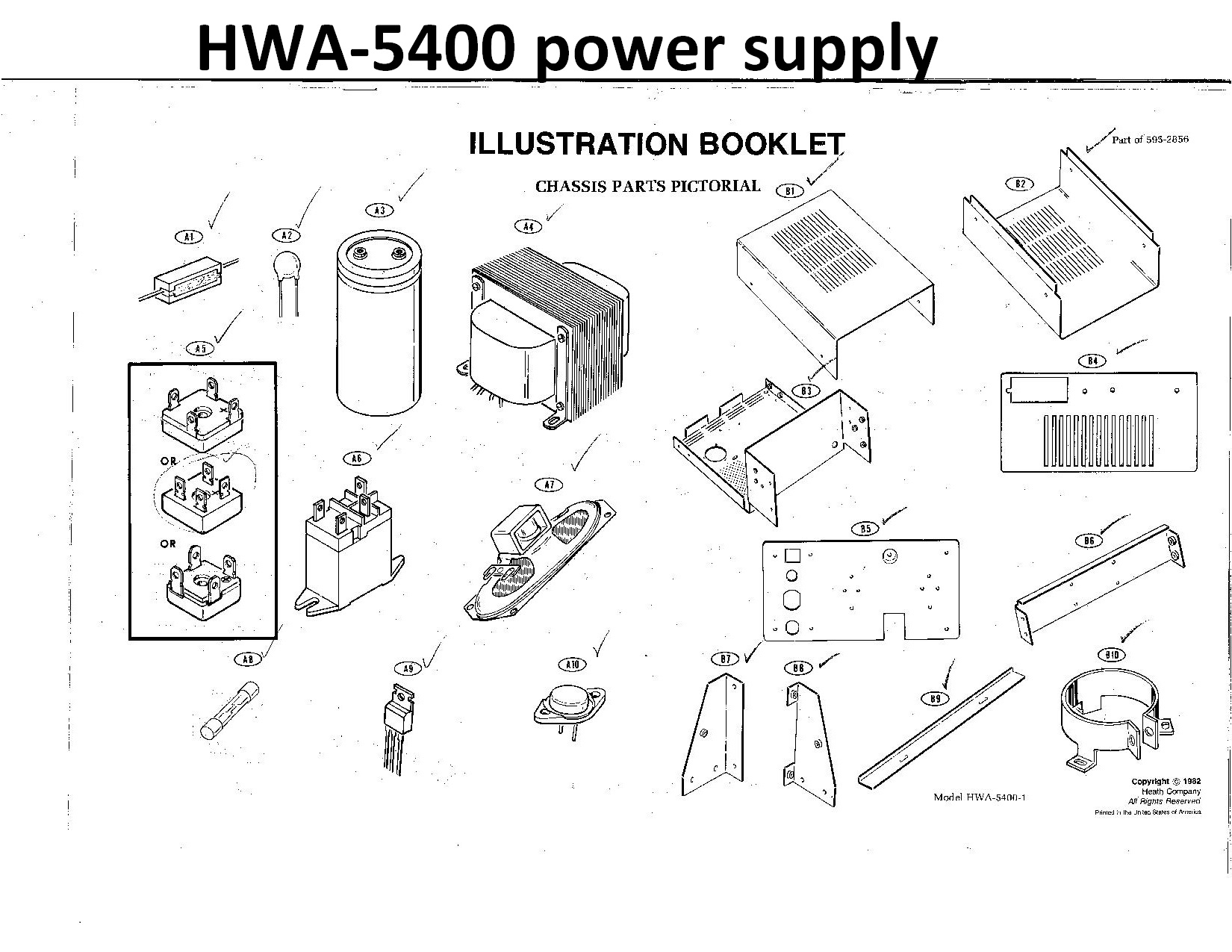
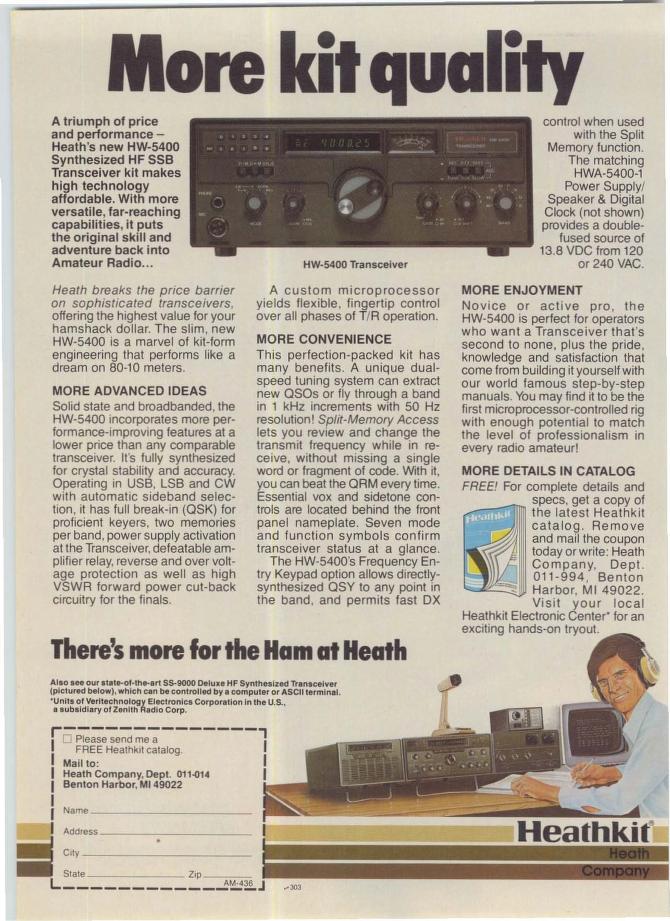
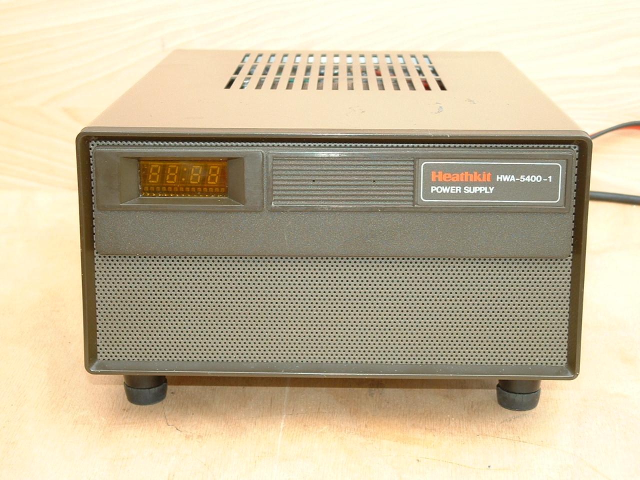
HWA-5400-1 Matching Power supply / Speaker / Clock
25Amp Linear power supply
I have this, but dont use it anymore. Due the the Linear nature of this supply, its gets very very hot. I use a small 30A switchmode.
HM-2140A SWR Meter (with Peak Detector & Remote monitor)
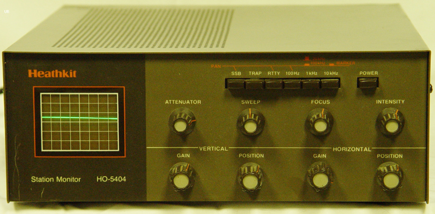
HO-5404 Station Monitor (with Panadapter)
Manual,Illustrations,Schematic, revisions,
HD-1481 Remote Coax Switch
SA-2500 Auto-Tuner
SA-2060A Manual Tuner
SB-1000 Linear Amplifier
HL-2200 Linear Amplifier
AMPLIFIER I am currently using
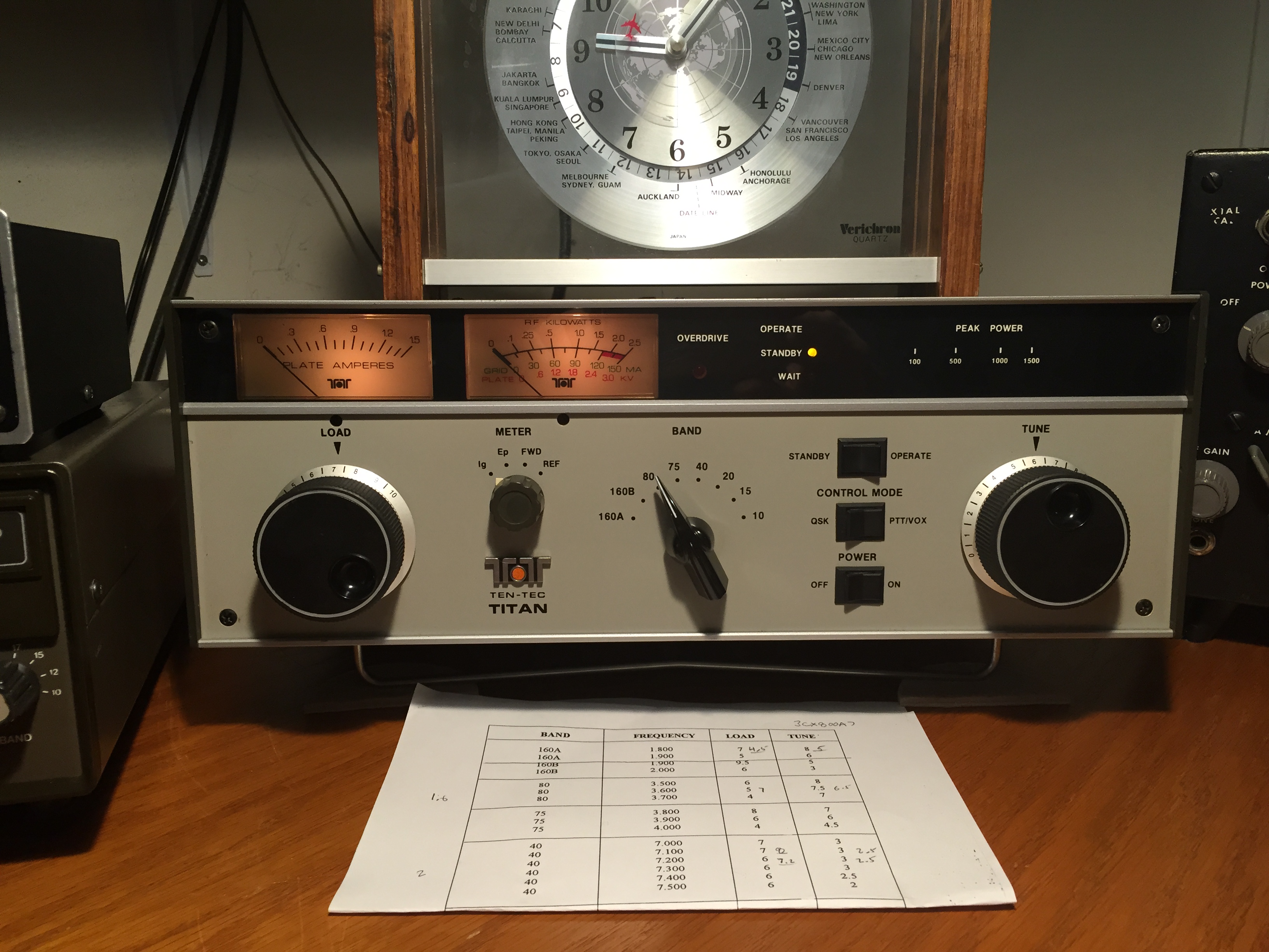
Ten-Tec Titan 425 using (2) 3CX800A7 EIMAC tubes for 1.5kw output at 60w input
The Titan is very tough, so nothing to worry about.
Just use TX3 RCA output to key the amp (double ended RCA cable from the Flex TX3 to the Titan PTT).
I use a MFJ-998 ANT tuner after the Titan.
Set STANDBY on the Titan, tune the ANT SWR flat with the MFJ-998. (unless your ANT is already flat)
Now Set OPERATE on the Titan.
Set the Titan LOAD and TUNE knobs half way.
Set PowerSDR Tune power level to 7.
Click the PowerSDR Tune button and adjust the Titan TUNE knob for max output
BUT keeping the GRID under 40mA all the time.
Adjust the Titan Load, But keeping the GRID under 40mA
Keep raising the PowerSDR Tune power level up (I usually go up to 38 on my Flex, but never more then 60), and use the Titan LOAD knob to keep the GRID below 60mA (turn clockwise to reduce the Grid mA). Use the Titan TUNE knob to get max output while using the Titan LOAD Knob to keep the Grid below 60mA
Make sure the SWR on the Flex is below 2:1 going into the Titan, otherwise you will need to use the ATU in the Flex as well.
If your SWR on the output of the Titan is low, you should be able to get 1500w output with 20w-60w input (keeping the Grid mA below 60mA) depending on the band and age of the tubes.
Write down the final Titan LOAD and TUNE knob positions on a piece of paper.
Then in the future (when you get a good feel for it) you can set both Knobs and set the PowerSDR Tune power output to 25 to simply verify that you have the Titan properly set.
When I talk SSB I usually set the Power output to 40 for 1500 watt peaks.
I recorded the middle of each band, and then just tweak the knob positions If I am above or below the middle of the band.
I always run in high voltage and low fan positions on the Titan.
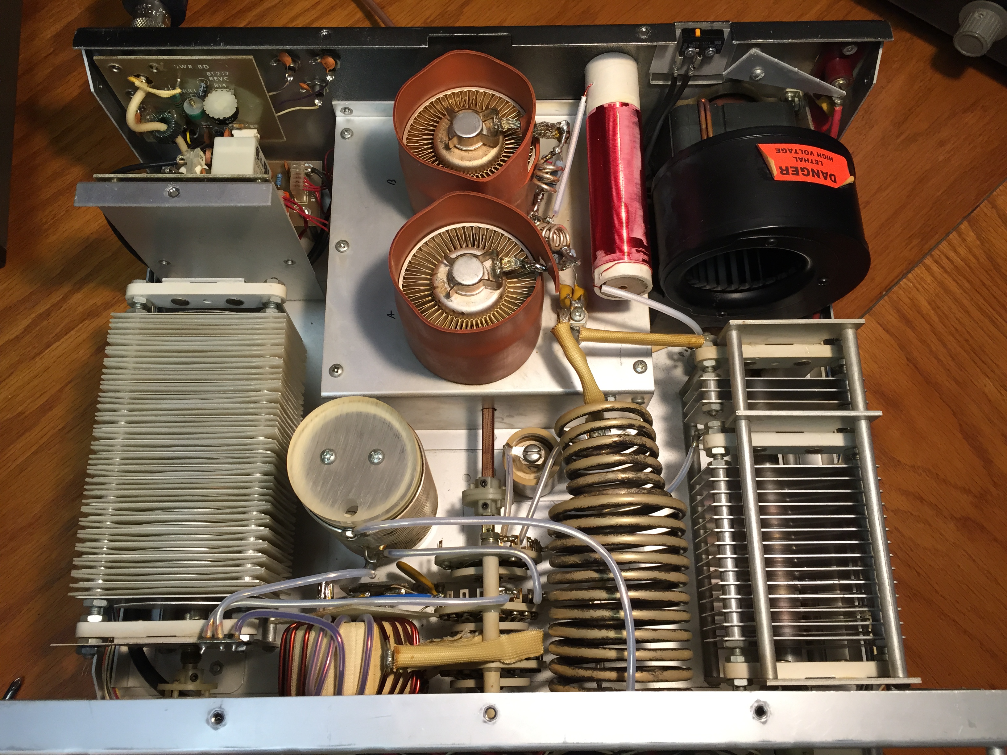
(Left) Inside of the Power supply (on the floor under the desk). (Right) Inside of the Titan Amp (on the desk)